Our website is made possible by displaying online advertisements to our visitors.
Please consider supporting us by disabling your ad blocker.
-
27-12-2017, 06:57 PM
#141

Toby, a good bet is the board the LCD is on. Post a picture of it as near to face on as you can get. Also maybe the DMX PCB has the RS485 chip onboard, meaning it'll likely also have 5V present. Should there be a little 8 pin chip on there, pin 8 will be +5V (or if you're unlucky, 3.3V) - and pin 5 will be 0V. Tip: Look at the chip where the part designations are readable (left to right). Pin 8 would be the top left & pin 5 would be at the top right.
Failing all that - you know there's a ready supply of 12V you can tap into - get yourself one of these: https://www.ebay.co.uk/itm/DC-DC-12V...ZwZjcWYmtvGMhw (you'll want the 5V output version). Another solution might be to buy a cheap in car USB charger & use the guts out of that
Last edited by Nakatomi; 27-12-2017 at 07:07 PM.
-
27-12-2017, 07:27 PM
#142
BTW all this wireless DMX stuff might just be about to be very old hat soon. I've started developing an ArtNet over wifi thing. The boards will be smaller & even assembled should cost about what UK sellers of Chinese wireless DMX boards currently charge.
-
27-12-2017, 09:45 PM
#143


Originally Posted by
Nakatomi

Toby, a good bet is the board the LCD is on. Post a picture of it as near to face on as you can get. Also maybe the DMX PCB has the RS485 chip onboard, meaning it'll likely also have 5V present. Should there be a little 8 pin chip on there, pin 8 will be +5V (or if you're unlucky, 3.3V) - and pin 5 will be 0V. Tip: Look at the chip where the part designations are readable (left to right). Pin 8 would be the top left & pin 5 would be at the top right.
Failing all that - you know there's a ready supply of 12V you can tap into - get yourself one of these:
https://www.ebay.co.uk/itm/DC-DC-12V...ZwZjcWYmtvGMhw (you'll want the 5V output version). Another solution might be to buy a cheap in car USB charger & use the guts out of that
I had a look on that board and it certainly looks promising. I have a 12-5 volt converter already, so thats also a possibility, but want to keep it simple and safe. I don't really want to be taking anything from the laser or other circuitry, especially the fans. 
I shall get a photo tomorrow.
-
28-12-2017, 06:35 AM
#144
-
28-12-2017, 08:57 PM
#145
See that there in the top photo with the black wire soldered to it? My bet is it's a voltage regulator. The output is likely on the middle pin (V_OUT). The black wire is likely 0V. The voltage.. may be 3.3V though. Other places I check are across capacitors (on your boards Toby they're the silver cans with black markings on them).

Last edited by Nakatomi; 28-12-2017 at 09:03 PM.
-
30-12-2017, 04:51 PM
#146
-
30-12-2017, 08:46 PM
#147

Originally Posted by
yourdj
Thanks for that I shall check that out. Very helpful.
i may be getting a wizard rush soon and was wondering where I would tap the DMX from on that.
I know its 5 pin, not used that before, but it may have an inbuilt 5 volt supply perhaps??
Any ideas?

Ahhh Wizards! Yes, I know these quite well & have modded a handful myself. It's an interesting voyage. Now, I can't remember precisely which model/version I had my greasy palms on - maybe they're all the same... The DMX is isolated - i.e. the DMX input has its own power supply and is actually electrically isolated from the rest of the unit - even the DMX output.
So. Somewhere on one of the boards (no, not near the DMX sockets, but where the loom from the DMX sockets leads) are a couple of relays, isolated DC-DC converter (these look like small black boxes EDIT: The isolated DC-DC converter is the black box in the photo below. The relay (singular) is actually orange). If you're trying to find which wire is DMX+ on the input for example BE CAREFUL. For why? Oh just that with the power OFF, the Wizard links DMX in to DMX out directly. When power is applied, the relays open which will disconnect the connection you had when it was powered off & DMX in data will be passed to DMX out over an isolated link. This is actually what the DMX standard advises (galvanic isolation is a REALLY very good idea in lighting - it means if mains ever ends up on a logic board, it can't wind up on a DMX cable - which WOULD fry anything & every other thing on the cable not similarly isolated).
Bet you're really glad you asked now. I wish I'd taken photos of the Wizard mods I did now. Maybe I did. I'll have a look.
EDIT: I looked, as promised.. and LOOK!

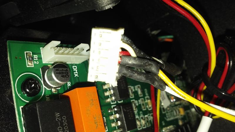
Explanation: Red is +5V for the wireless DMX board. Black is 0V. In the 1st photo I'm picking up power via the opto-isolator (it's on its own power supply separate from the rest of the unit).
Yellow & white DMX wires are tapped into the loom & heatshrinked. I chose this method as the least invasive route.
Last edited by Nakatomi; 30-12-2017 at 09:03 PM.
-
05-01-2018, 08:22 PM
#148
Originally Posted by
Nakatomi
See that there in the top photo with the black wire soldered to it? My bet is it's a voltage regulator. The output is likely on the middle pin (V_OUT). The black wire is likely 0V. The voltage.. may be 3.3V though. Other places I check are across capacitors (on your boards Toby they're the silver cans with black markings on them).
I touched a multimeter on the bit on the right (there are 3 cables within the circle) and it caused the unit to operate.
Do I need to solder the power to the bit on the left where the line ends?
Either or, I saw a slight bit of voltage but after that nothing was showing up?
Anyhow I am sure it says 3.3 on the little board???
-
06-01-2018, 09:51 AM
#149
Originally Posted by
yourdj
I touched a multimeter on the bit on the right (there are 3 cables within the circle) and it caused the unit to operate.
Do I need to solder the power to the bit on the left where the line ends?
Either or, I saw a slight bit of voltage but after that nothing was showing up?
Anyhow I am sure it says 3.3 on the little board???
Put your multimeter ground (black) probe where you definitely know (or have a large degree of confidence in) there's 0V - e.g. a DMX socket. Then with the red lead measure the pins of the device circled in yellow. The leftmost pin - the tab - which is where the line ends - is likely commoned to the middle of the 3 pins at the other side of that device - and in all likelihood will be a regulated voltage. Maybe 5V, Maybe 3.3V which is why you're measuring it - to find out.
-
06-01-2018, 11:32 AM
#150
Originally Posted by
Nakatomi
Put your multimeter ground (black) probe where you definitely know (or have a large degree of confidence in) there's 0V - e.g. a DMX socket. Then with the red lead measure the pins of the device circled in yellow. The leftmost pin - the tab - which is where the line ends - is likely commoned to the middle of the 3 pins at the other side of that device - and in all likelihood will be a regulated voltage. Maybe 5V, Maybe 3.3V which is why you're measuring it - to find out.
Its 3.3.
The unit has several spare 12 volt molex sockets, so will put my step down off that. Its safer than proving about in places I am unsure of.
 Posting Permissions
- You may not post new threads
- You may not post replies
- You may not post attachments
- You may not edit your posts
-
Forum Rules


 Reply With Quote