Our website is made possible by displaying online advertisements to our visitors.
Please consider supporting us by disabling your ad blocker.
-
-
-


Originally Posted by
Imagine

I know this is a very old one - but my Acme Jaguar MSD's take the CA-8 connector which I'm reading is also 5v

Any idea which pins you used to get the supply Julian? I'm drawing a blank on the board at the moment

The one on the right that has nothing connected (should be 2 spare pins). Get a multi meter just to check anyway.
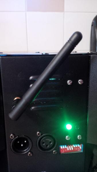
I have soldered it to the back of the boards where I have had the room to do so.
I have put the arial in the actual light now so its out the way. Does not affect range much I don't think?
-

Originally Posted by
Imagine
I know this is a very old one - but my Acme Jaguar MSD's take the CA-8 connector which I'm reading is also 5v
Any idea which pins you used to get the supply Julian? I'm drawing a blank on the board at the moment
I honestly can't remember without taking apart the connectors - multimeter + 5mins should tell you which is which  From memory though, ground is one of the end pins.
One other slightly odd thing to mention about the CA9 connector is that it doesn't come live unless the fixtures are in DMX mode (e.g. not in sound to light or master/slave) and they also don't come live until 30 seconds after the units enter DMX mode! This caught me out a few times while I was originally testing the setup, but it seems to be consistent behaviour across the Acme Kit fitted with CA9 connectors (I've seen it on my Cougars and on some Acme Micro Fusion's).
As for CA8 - I've no clue. I've had the controllers apart a few times and they look like a common line and two bi-directional signal lines that are used to light the LED's on the controllers AND detect when the line is shorted to common. Again - pull out a meter and I'm sure you'll find out what's what quickly enough. If you're fitting the PCB's internally though, it's worth digging around a little more as I'm sure there'll be a 5V line somewhere, just look for a LM series voltage regulator...
Julian
-

Originally Posted by
DJ Jules
One other slightly odd thing to mention about the CA9 connector is that it doesn't come live unless the fixtures are in DMX mode (e.g. not in sound to light or master/slave) and they also don't come live until 30 seconds after the units enter DMX mode!
Ahaaaa....now THAT might explain a lot! I literally turned it on, probed, couldn't find anything and put it back together again. Will try that again tomorrow. I did think it a little odd though as there should be something there to power the LED in the handset.
Originally Posted by
DJ Jules
As for CA8 - I've no clue. I've had the controllers apart a few times and they look like a common line and two bi-directional signal lines that are used to light the LED's on the controllers AND detect when the line is shorted to common. Again - pull out a meter and I'm sure you'll find out what's what quickly enough. If you're fitting the PCB's internally though, it's worth digging around a little more as I'm sure there'll be a 5V line somewhere, just look for a LM series voltage regulator...
Julian
Not that I can find
I've got down as far as an 8v which is on a spare 2 pin Molex which would have been a nice way of doing things (the only other spare Molex is 12v), but can't find anything as low as 5v.....yet.
To be honest though if I can get a 5v connection on the controller line, it's in the ideal position on the MSD250 (think Wizard and you'll see the shape I'm dealing with).
-
Originally Posted by
yourdj
The one on the right that has nothing connected (should be 2 spare pins).
Originally Posted by
DJ Jules
ground is one of the end pins.
Ahem 
-
Originally Posted by
yourdj
The one on the right that has nothing connected (should be 2 spare pins). Get a multi meter just to check anyway.
I have soldered it to the back of the boards where I have had the room to do so.
I have put the arial in the actual light now so its out the way. Does not affect range much I don't think?
Just to attribute and acknowledge Toby's contribution 
-
Originally Posted by
spukemonkey
after reading this forum I brought a pcb and decided to give it a go on my trilex :-)
Power was pulled off the 12v line and dropped down using a l7805 and a 10uf 63v cap. the dmx side of it was soldered direct to the pins on the back of the in plug.
Okaaaay.....'scuse my ignorance here. I have a grasp of proper electric, but once you start talking about components I get lost.
So - taking the above.....I know the l7805 is a voltage regulator and the 10uf 63v cap is a capacitor (I can be clever when I want to be).
Having had another look in the back of this beast, I think my safest option is to connect to the spare 12v molex that's in there (saves putting the soldering iron anywhere near the board and causing possible problems). So, would I be right in thinking that I go from the positive of the 12v pins, out to the l7805, then along to the capacitor (i.e. along a small lump of bread-board to keep things tidy) and finally into the wireless board, taking the ground from the board back to the other side of the molex? Is it that simple?
If so, that's the route I'll go as it's the least modification to the main board in the fixture itself. Connecting to the back of the XLR is no problem, but seeing the complexity of the main board in there I think it's one that's best left well alone 
-
-
Originally Posted by
Imagine
Having had another look in the back of this beast, I think my safest option is to connect to the spare 12v molex that's in there (saves putting the soldering iron anywhere near the board and causing possible problems). So, would I be right in thinking that I go from the positive of the 12v pins, out to the l7805, then along to the capacitor (i.e. along a small lump of bread-board to keep things tidy) and finally into the wireless board, taking the ground from the board back to the other side of the molex? Is it that simple?
Essentially, yes, except the 7805 has three pins: input, output and ground, so also needs to be connected to ground. Good tutorial here (and definitely use vero/strip board, not bread board - you don't want anything drifting out in transit).
http://www.instructables.com/id/5v-Regulator/
Julian
 Posting Permissions
- You may not post new threads
- You may not post replies
- You may not post attachments
- You may not edit your posts
-
Forum Rules


 Reply With Quote
